Tuesday, August 1, 2017

The Normal Forms: Introduction

Normalization is a methodology for minimizing redundancy in a database without losing information. It is the theory behind the arrangement of attributes into relations. The rules which govern these arrangements are called Normal Forms.

In What Is Normalization: Parts I, II, III, IV and V, I discussed the decomposition method of normalization, where you put all your fields into a single table and break the them down into smaller, normalized tables.

In Entity-Relationship Diagramming: Parts I, II, III, and IV, I discussed an alternate method which works from the bottom up. It takes the individual pieces of information (Attributes) and group them into logical groupings (Entities).

However, in neither case did I formally define or explain the Normal Forms. And that's for good reason. I find that only after people get a working understanding of normalization do they really understand the Normal Forms and what they imply. Therefore I usually leave them until last. If you haven't read the above mentioned serie, it would be worth your while to do so.

Normalization was first developed by E. F. Codd, the father of Relational Database theory. He created a series of "Normal Forms", which mathematically defined the rules for normalization. Each normal form is "stronger" than the previous, that is, they build upon the previous normal forms. Second Normal Form (2NF) encompasses all the rules of First Normal Form (1NF) plus adding its own rules. Third Normal Form encompasses all of 1NF and 2NF, and so on.

Figure 1: Each Normal Form Encompasses the Previous


In order, the normal forms are: First Normal Form (1NF), Second Normal Form (2NF), Third Normal Form (3NF), Boyce-Codd Normal Form (BCNF), Fourth Normal Form (BCNF), Fifth Normal Form (5NF), and Domain Key Normal Form (DKNF). BCNF comes between 3NF and 4NF because it was developed later, but because of its "strength" belonged between 3NF and 4NF.

Since each normal form encompasses all previous forms, in theory, the higher the normal form, the "better" the database.

In practice, however, normalizing to the first three normals form will avoid the vast majority of database design problems. So it is generally agreed that to be properly normalized, most databases must be in 3NF.

Beyond 3NF, the normal forms become increasingly specialized. Boyce-Codd Normal form and Fourth Normal Form were created to handle special situations. Fifth Normal Form and Domain-Key Normal Form are largely of theoretical intererst and little used in practical design.

So what I'm going to do for this series is limit myself to the first three normal forms, giving their definitions, implications for data, and how to implement them.

In my next post, I'll start with the First Normal Form.

Friday, June 23, 2017

Entity-Relationship Diagramming: Part IV

In Entity-Relationship Parts I, II, and III, I described a method of normalization that builds up from individual data elements. Following this method results in a database design that is normalized to the Third Normal Form -- without having to know what the Normal Forms are.

(I haven't discussed the Normal Forms. Perhaps I will in a later post.)

In Part III, I left off with the completed Entity-Relationship Diagram shown in Figure 1.

Figure 1: Employee Database E-R Diagram


When I do E-R diagramming, I like to ignore the attributes, concentrating instead on just the entities and their relationships. But at some point, obviously, the attributes have to come back into it. I like to save that to the end.

There are some good E-R diagramming tools available out there, like Visio and ERWin, but for small projects, I usually just implement the tables directly in Access and create the Relationships there. The Access Relationship Window works pretty well as a diagramming tool, and you've got a completed database at the end.

Implementing an E-R Diagram

So far, I've talked about Entities and Attributes. I do that deliberately to keep myself from thinking about implementation issues while I'm designing the data model. But at the implementation phase, entities become tables and attributes become fields.

The first thing I do is add an Autonumber, Primary Key field (Surrogate Key), to each table, naming it after the table with a suffix of "ID". Thus the tblEmployee table will have a field EmployeeID. Then I create a Unique Index on the Natural Key I identified during E-R diagramming process.

At this point, my tables look like Figure 2.

Figure 2: Tables with Surrogate Keys Added


Now it's time to look at my relationships. Relationships are created on fields holding related information, Primary Key to Foreign Key. In a One-to-Many (1:M) relationship, the primary key of the table on the "One" side is added to the table on the "Many" side table and becomes the foreign key.

Since there is a 1:M relationship between tblEmployee and tblEmployeeCertification, I'll put EmployeeID in EmployeeCertification and it will become the foreign key for tblEmployee.

I'll do the same with every relationship. The resultant tables look like Figure 3.

Figure 3: Tables with Foreign Keys Added


Lastly, I need to create the actual relationships. I do this by clicking and dragging the primary key of one table into its corresponding foreign key in the other. For instance, I'll click on EmployeeID in tblEmployee and drag it to EmployeeID in tblJobHistory.

When I do, I will get an "Edit Relationships" dialog box shown in Figure 4.

Figure 4: Edit Relationships Dialog Box


The Referential Integrity box will not be checked by default. However, you MUST check it in order to create a true relationship. Without it, Access will create a line between the tables, but it will NOT be a relationship.

When you click the Referential Integrity box, Access should correctly identify the relationship as a One-to-Many relationship. If it does not, if it says Indeterminate, you've done something wrong.

Clicking OK results in the relationship being created. Figure 5 shows that.

Figure 5: Relationship Between tblEmployee and tblJobHistory.

Now, I'll just do that for the rest of the relationships, and I'm done.

Figure 6: Completed Data Model

The process I've outlined here is really just the bare bones. If you're interested in seeing examples in more detail, you can find some in the Tutorials: Database Design section of my website.


.

Tuesday, June 13, 2017

Entity-Relationship Diagramming: Part III

In this Entity-Relationship series, I'm attempting to present an alternative to standard, decomposition-style normalization.

In Entity-Relationship Diagramming: Part I, I grouped all the objects in my business narrative into either Entities or Attributes. Entities are groups of Attributes and Attribute describe Entities.

In Entity-Relationship Diagramming Part II, I defined the relationships between my entities. Relationships store information about how your Entities interact. Figure 1 shows where I left off.

Figure 1: Relationships Between Entities.


Unfortunately, I'm not done yet, for two reasons: 1) as I said in What is Normalization: Part V, many-to-many relationships cannot be directly implemented in a relational database, and 2) I still have an unassigned attribute. So first I'll rationalize the many-to-many relationship and then take another look.

To rationalize a many-to-many relationship between two tables, you create a third table -- an "intersection" or "linking" table. Then you create one-to-many relationships between the linking table and each of the main tables, with the "many-side" of both relationships on the linking table.

As you can see above, Employee and Certifications have a many-to-many relationship, so I need to create a new entity (Employee/Certifications). Sometimes linking tables have logical names. Other times, they don't. In that case, I simply combine the names of the base tables.

Figure 2 shows how the rationalized relationship is diagramed.

Figure 2: Rationalized Employee-Certification Relationship

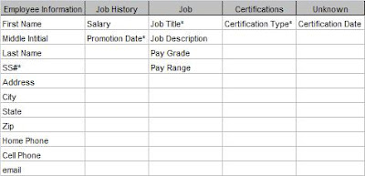
Now I can see where to put my unassigned Certification Date field. The Employee/Certification entity represents a certification for a particular employee and that can be given at only one time. Therefore the Certification Date field goes in this new entity. Figure 3 shows the completed Attribute Grid.

Figure 3: Final Attribute Grid


Now that I've got all the relationships between my entities identified and assigned all the attributes, I can put it all into one diagram.

Figure 4: Final E-R Diagram

Now I've got all the pieces. All that's left is to implement my diagram in Access (or some other database). In Entity-Relationship Diagramming: Part IV, I'll do just that.

.

Tuesday, June 6, 2017

Entity-Relationship Diagramming: Part II

In my last post, Entity-Relationships Part I, I approached the idea of normalization from a different point of view. Rather than breaking a large table into smaller, normalized tables, the Entity-Relationship process starts with the individual pieces and builds it up into a properly designed data model. It uses objects (Entities and their Attributes) and looks at the real-world Relationships that exist between them. The end result of this is an Entity-Relationship Diagram.

I started the process by writing a short narrative of the database requirements and grouping all the nouns into related categories. A few could not be assigned. Figure 1 shows the resultant grid.

Figure 1: Entity-Attribute Grid

At this point, I should say that this is not a strictly linear process . That is, you can't always move smoothly from one step to the next. Sometimes you have to move back and forth between them as you discover more things about your system.

That's what I'm going to do next. Because I have an unassigned attribute, I'm going to look at the relationships between my existing entities and see if something doesn't present itself.

To look at the relationships, I'm going to ignore the attributes for a while. Attributes do not have relationships, only entities do. If you discover that an attribute does have a relationship with some other entity or attribute, that's an indication that it is really an entity and your grid must change.

First, I'll determine the relationships between existing entities. In What Is Normalization, Part IV , I describe the different types of relationships: One-to-One (1:1), One-to-Many (1:M), and Many-to-Many (M:M). Then I'll diagram them in pairs.

The diagramming technique I'll use is one of the simplest. Entities are represented by boxes . Relationships between entities are represented by lines. "Crow's feet" show a "many-side" relationship and a vertical bar shows a "one-side" relationship. Figure 2 shows how the relationship types are represented.

Figure 2: Relationship Types

Many-to-Many: Common in real life, but cannot be represented in a database.
One-to-Many: The most common relationship in a database.

One-to-One: Seldom used.


So how do I know what the relationships are for my Employee Database? For that I need to go back to the narrative. The second paragraph describes "business rules", that is, how the business actually works. I'll repeat the paragraph here.

An employee can have multiple jobs over time, (ie, Analyst, Sr. Analyst, QA Administrator). Employees can also earn certifications necessary for their job.

From this I can write out the relationships in full sentences, and I find it useful to write them in both directions. For instance, from the narrative, I can say:

Employee-JobHistory
Each Employee can have One or More Job History instance
and
Each Job History instance can be for One and Only One Employee.

This is a classic One-to-Many relationship and we will diagram it as follows:

Job-Job History
Each Job can have One or More Job History instance
and
Each Job History instance can be for One and Only One Job.

Another One-to-Many relationship diagrammed as follows: Employee-Certifications
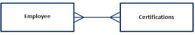
Each Employee can attain One or More Certifications
and
Each Certification can be earned by One or More Employees

This is a Many-to-Many relationship, and this will need additional work, but I'll leave it for now.
Job-Certifications
It might seem that there is no relationship between Job and Certifications, except for the word "necessary" in the narrative. In going back to the client, I discovered that certain certifications are necessary in order to be promoted to some jobs. Thus there IS a relationship as follows:

Each Job requires One or More Certification
but
Each Certification is for One and Only One Job

Another a One-To-Many relationship 
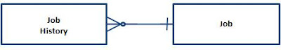
Each certification is only for a single job. It is important to verify this with the client. If a certification were required for many different jobs, the model would be different, but in this case it is for only one job. The certification requirements for Analyst I are different than for Analyst II.

These sentences are extremely useful when communicating with your client (or even if you're developing the database for yourself). If the client can say that each of the sentences is strictly true, then you'll know you've designed it correctly. If any of the sentences are wrong, you have to go back and re-evaluate your design.

Unfortunately, as I said in What Is Normalization, Part V , many-to-many relationships cannot be represented directly in a relational database. So I'm going to have to add some intersection (or "linking") tables.

I'll take care of that next in Entity-Relationship Diagramming: Part III

.

Wednesday, May 31, 2017

Entity-Relationship Diagramming: Part I

In the last series, Normalization Parts I, II, III, IV, and V, I approached normalization from a particular point of view. I put all the information into a single table then removed redundancies into separate tables. This method is called decomposition. Decomposition is fine for understanding the theory of normalization and for creating small databases. However, it is less useful for large databases. At least, I've found it so.

So I'm going to talk about another way to approach normalization that starts with the individual pieces and builds it up into properly normalized tables. This method is called the Entity-Relationship method and the final result is an Entity-Relationship Diagram. An E-R diagram is useful not just for creating the data model, but for documenting it as well.

Since we've been working with the Employee Database in our other examples, let's stick with it. But since I claimed that E-R method works for more complicated designs, let's make it a little more complex. I like to start with a short narrative of the requirements.

Narrative

ZYX Laboratories requires an employee tracking database. They want to track information about employees, the employee's job history, and their certifications. Employee information includes first name, middle initial, last name, social security number, address, city, state, zip, home phone, cell phone, email address. Job history would include job title, job description, pay grade, pay range, salary, and date of promotion. For certifications, they want certification type and date achieved.

An employee can have multiple jobs over time, (ie, Analyst, Sr. Analyst, QA Administrator). Employees can also earn certifications necessary for their job.

Next, I take the narrative and underline all of the nouns. (I'm going to bold them here because Blogger doesn't have underlining.)

Narrative 2

ZYX Laboratories requires an employee tracking database. They want to track information about employees, the employee's job history, and their certifications. Employee information includes first name, middle initial, last name, social security number, address, city, state, zip, home phone, cell phone, email address. Job history would include job title, job
description
, pay grade, pay range, salary, and date of promotion.
For certifications, they want certification type and date achieved.

An employee can have multiple jobs over time, (ie, Analyst, Sr. Analyst, QA Administrator). Employees can also earn certifications necessary for their job.

All of these nouns must be represented in the database -- some as Entities and some as Attributes. An Entity is a "thing" about which we store information. An Attribute is the information that is being stored.

So the next task is to group the nouns into logical groupings. At first pass, it appears that there are three entities: Employee Information, Job History, and Certification. It is useful at this point to put them in a grid and assign the rest of the attributes like Figure 1.

Figure 1: Attribute Grid

Next, I need to assign primary keys to each entity. (At this point, I call them "entities" rather than "tables".) As I said in What Is A Primary Key?, a primary key is a field or fields which uniquely identify a record. At this point, I'm dealing only with natural keys. Figure 2 shows the primary keys.


Figure 2: Attribute Grid with Primary Keys

Now we go back to our entities and look for two things:

  1. see if each attribute can have only one value for that entity, and
  2. see if each attribute truly belongs to the entity.

To determine the second, we look at "functional dependencies", which just means that each field's value depends on the value of the primary key.

So, for the Employee table, a person (as represented by the SS#) can have only one first name, last name, address, home phone, and so forth. That satisfies requirement #1. Secondly, if the value of the SS# changes, then so will all of those values. By that, I mean if we move to a different entity with a different SS#, that entity will have a different first name, last name, etc. (For our purposes here, we will assume that no two employees share any of these attributes.)

Now, what about the Job History table? Any time an entity has a compound primary key, you should look at it very closely to make sure all the fields depend on the entire primary key. Any particular job can have only one description, pay grade, and pay range. However, none of those depend on the Promotion Date.

I've got a problem here and I need to take another look. What I really have is information about two different "things".

Job Title, Description, Pay Range and Pay Grade pertain to the Job as a category. Everyone who holds that position will have the same values. On the other hand, Salary and Promotion Date will be different for each person. So I really have two entities: 1) Job (information about the job itself), and 2) Job History (information about a particular employee's employment history.

I need take Job Title, Description, Pay Range and Pay Grade out of the Job History table and put them in the Job table.

Lastly, in the Certification table, Certification Date is also not fully dependant on the Certification Type. Different individuals achieve the certification at different dates. I don't have an entity to put the date in, so I'll put that to the side and come back to it later.

Figure 3 shows the amended grid.


Figure 3: Amended Attribute Grid

At this point, it is useful to look at the Relationships between these Entities. We may be able to find a place to put our unassigned attribute. But I'll save that for the next post: Entity-Relationship Diagramming: Part II.

.

Tuesday, May 16, 2017

What Is Normalization: Part V

Many-to-Many Relationships

In What Is Normalization, Part IV, I discussed the three basic kinds of relationships: One-to-One, One-to-Many, and Many-to-Many. In this post, I'll concentrate on the many-to-many.

Many-to-Many (M:M)
In real life, M:M relationships are extremely common. Each customer can order many products, and each product can be ordered by many customers. In high school, each teacher has many students, and each student has many teachers. At a conference, each attendee attends many sessions, and each session has many attendees.

Returning to our Employee Database example, suppose we want to store a job description as well as the salary history. Since each employee can hold many positions over the course of his or her career, and each position can be held by many employees, we have a many-to-many relationship. So let's go back and change our original table and see how we can normalize it.

Figure 1: Expanded Employee Table (Non-Normalized)

You'll notice that I've changed the SS# field in favor of an EmployeeID field. SS# is a really bad field for a primary key. You still might want to store SS#, but not for a primary key, so I'm leaving it out of this example.

Like the example in What Is Normalization Part II, the table has redundant data, and so it needs to be normalized. And just like in Part II, I'll remove the redundant Employee information into its own table, like so:

Figure 2: Employee Table

Figure 3: Job History Table


But looking at the Job History Table, we can see that we still have redundant data. Job Description is repeated several times. Unfortunately, we don't have a convenient linking field as we did with the EmployeeID field in the Employee Table. So we'll have to make one up. When you make up a primary key, as opposed to using an already existing field for your primary key, it is called a surrogate key. I discuss the difference between surrogate keys and natural keys in What is a Primary Key?

So, in order to remove the job description information, I'll create a table called Job Description and fill it with just one instance of each value. Then I'll also add a field called JobID, and fill that will it with unique values, thus creating a surrogate primary key. Next, I'll return to the Job History table and replace the job descriptions with the corresponding JobIDs. Like this:

Figure 4: Revised Job History Table

Figure 5: Job Types Table


Okay, so what does this have to do with Many-to-Many relationships? Well, if you look at Employee and Job Types, you can see that there is actually a many-to-many relationship between these tables. Each Employee can have many Job Types over time and each Job Type can apply to many Employees.

Unlike one-to-one and one-to-many, many-to-many relationships cannot be directly represented in a relational database. In order to create one in a database, we have to have an intersection table (also called a "linking table"). In this case, the linking table already exists: Job History.

To represent this M:M, you create a relationship between each of the main tables (Employee and Job Types) to the linking table (Job History), with the "many-side" on the linking table. The final relationship will look like this:

Figure 6: Many-to-Many Relationship Implemented


Notice that each primary key of the main tables is represented as a foreign key in the linking table, and while each of the foreign keys is part of the primary key of the linking table, neither is the entire primary key.

So far, I've approached Normalization from a particular perspective. I've put all the information into a single table, looked for redundant data, and removed the redundancy into a separate table. This approach is called "decomposition". It works very well for simple data models, but becomes unwieldy in complex models.

However, there is another approach that has proven easier for me to work with very complex data models. This approach is called Entity-Relationship Diagramming. In Entity-Relationship Diagramming: Part I, I'll talk about that.

.

Monday, May 1, 2017

What is Normalization: Part IV

More Relationships

In What Is Normalization, Part III, I discussed how to create a relationship to join our normalized tables back together so that no information was lost in the normalization process.

There are three basic kinds of relationships: One-to-One, One-to-Many, and Many-to-Many.

One-to-One (1:1)
A marriage is an example of a 1:1 relationship. A husband can have one and only one wife and a wife can have one and only one husband. Of course, in the real world, there are exceptions to this, but let's accept this as a general case.

To implement a one-to-one relationship, you must have a primary key in both databases, which stores the same information, SS# for example. So continuing with our employee database example, suppose we had a ContactInfo table which stored Address, City, State, Zip, and Phone.

In this simplified example, we'll assume that people have a single address and phone. The primary key for this table would also be SS# since each record in the ContactInfo table represents the contact information for a single employee.

To create the one-to-one relationship, I would click and drag the primary key from Employee (SS#) to the primary key of ContactInfo (also SS#). Although the fields are named the same in this example, they do not have to be, however, they MUST represent the same information. In the Relationship Window, it would look like Figure 1.


Figure 1: One-to-One Relationship


Notice there is a 1 on each end of the relationship.

In relational databases, 1:1 relationships have limited utility. In most cases, the data elements from both tables can be combined into a single table.

One-to-Many (1:M)

This type of relationship is also known as the parent/child relationship for good reason. If we consider a biological parents only, we can say each mother can have one or more children and each child can have one and only one mother.

As I showed in Part III, the relationship between Employee and Salary History is a one-to-many relationship where each record in the employee table can be related to multiple records in the Salary History table, but each record in Salary History is related to only one record in Employee.

To implement this type of relationship, you must have a field in the "child" table that corresponds to the primary key in the "parent" table. Again, this field is SS# in our example, However, unlike the one-to-one relationship, it is NOT the primary key of Salary History, although it may be part of the primary key. Figure 2 shows this relationship.


Figure 2: One-to-Many Relationship


One-to-Many relationships are extremely common in relational databases.

Many-to-Many (M:M)

In real life, M:M relationships are extremely common. You'll notice that in both the other illustrations, I had to qualify the definition of both a marriage and parent/child. That's because real world definitions are messy. In some places in the world, a man can have multiple wives and a woman, multiple husbands. Sometimes simultaneously. Children can have more than one parent. In the real world, these relationships many-to-many.

Because many-to-many relationships are common in the real world, we must also know how to represent them in relational databases. Unfortunately, M:M relationships cannot be represented directly. They must be represented indirectly by a linking table and a pair of 1:M relationships.

In What Is Normalization: Part V, I'll show how.

.